Opis
2D/3D CAD/BIM program s podrškom za AutoCAD DWG format. Osnovni 2D/3D elementi za arhitektonsko projektiranje (zidovi, prozori, vrata, stepenice,…), 2D import iz ArCona. Osnova ArCADia BIM sustava. Uključene osnovne funkcije projektiranja instalacija. Engleski jezik.
What is ArCADia?
ArCADia is a program supporting 2D and 3D design, based on a well-known and developed for many years CAD platform, which guarantees full compliance with the DWG format that closely resembles the AutoCAD program.
New tools and featers of the ArCADia BIM 12:
- New option of inserting a single wall by an edge,
- Tutorial videos available at command icons,
- Animated object library, sun animation and scene cloud cover selection, saving project tour in the mp4 format,
- PBR texture library,
- Floating data input window at cursor,
- Creating a three-dimensional CAD project from ArCADia’s objects (walls, pipes, cables etc.),
- New auxiliary options placed in a special group and easily accessible from the left toolbar,
- New options for measuring length, area and perimeter.
ArCADia software features:
- Support BIM technology, object-oriented architectural design.
- Ready-made architectural elements: multilayer walls, stairs, bases, columns, chimneys, windows and doors.
- Comparing and merging documents.
- Automatic floor entry, additional support for Teriva ceiling design.
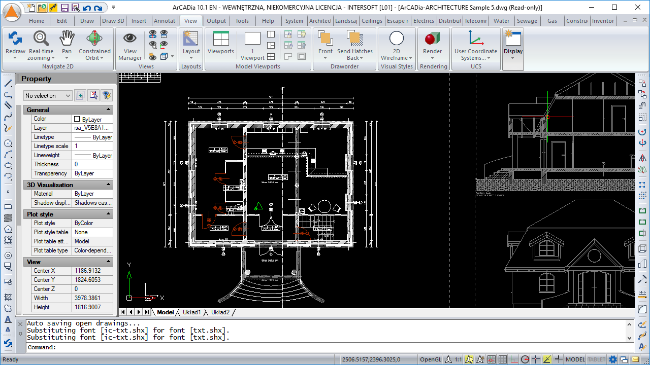
- Drawing of flat and spatial technical documentation and its writing to the native DWG format characteristic of most CAD applications.
- Work on layered drawing with the ability to use groups, blocks, external references and raster backdrops.
- Precise drawing with the ability to use Cartesian and polar coordinates, characteristic points and tracking.
- Work on a real-world model with the ability to print at any scale on a specified sheet of paper.
- Generating statements.
- Supporting the IFC format. A possibility to exchange design data with other programs.
Basic tools of the ArCADia BIM system:
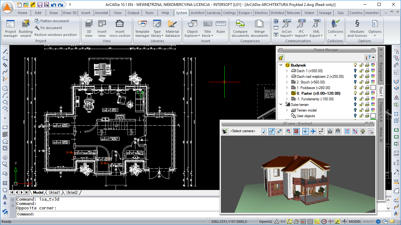
- Managing views and the displayed information through the clear tree of the Project Manager.
- Inserting elements such as wall, pipe, etc. using the smart tracking function.
- Showing elements drawn in the view in a classic or the new 3D view rendered in real time (visualization using a 3D game engine).
- A smart list of the most often used commands (Smart TOP 10) that are automatically memorized when working on a project, creating a personalized tool palette.
- The possibility to compare two versions of a project created as an ArCADia system model in the scope of new and modified system elements.
- The possibility to merge the building model from an architectural design with the installation design models to create one complete model of a building project
- Collisions list of all or individual ArCADia system elements on a view, 3D view and a clear list.
- Built-in library that allows for detailing with 2D symbols and 3D objects needed in the drawing.
- Creating and inserting drawing tables with the option of saving them to the program library
- Saving custom settings for elements (pens, fonts, default element sizes, etc.) in the project template.
- Built-in library of all elements types, with the possibility of expansion
- Possibility of entering linear and angular dimensioning.
- Precise printing by setting all print parameters.
- Working in DWG 2018 native format.
Architecture
- Choice of defined or drawing any multilayer wall.
- Built-in catalogue of construction materials based on the following standards: PN-EN 6946 and PN-EN 12524.
- Inserting of window and door woodwork in a parametric way.
- Inserting single chimney openings or shafts, i.e. groups of chimneys with a given number of columns and rows.
- Automatic creation of rooms from the closed outlines of walls and virtual walls, with assigning names, functions, temperature and lighting demand.
- Defining one- and multi-flight stairs and winder stairs in any view.
- Inserting automatic ceilings on the closed external walls contour.
- Creating a level with the possibility of copying selected elements.
- Inserting an automatic roof on the closed external walls contour.
- Inserting of roof windows and dormer windows.
- Inserting woodwork and rooms lists.
Construction
- Module for constructing the structural systems of Teriva ribbed-beam roofs, containing all the basic elements of the system: ceiling beams, reinforcing ribs, hidden ribs, exchanges, supporting mesh and additionally all necessary material lists including the elements needed to make the ceiling, completed with reinforcing steel and monolithic concrete .
- Inserting the binding joist with the insertion of longitudinal reinforcement and stirrups.
- Automatic 3D construction view created on the basis of a three-dimensional architectural model of a building.
- Transferring both the location and the material as well as the bar cross-section to the construction view. Passing the remaining elements of the architectural model in the form of a rendered or translucent 3D view, and in the case of modular axes, bar elements and surface elements also in the form of their active underlay.
Water supply installations
- Creating drawings of the internal water supply system, from the connection point, through the water meter set and pipelines, to the necessary fittings and draw-off taps.
- Applying risers and distribution pipes from a library of pipes made of various materials. It is possible to simultaneously run several parallel conduits with different functions and connect them intelligently. Drawing simplifications that allow you to change the level of many elements of the installation at the same time.
- Inserting fittings and devices from the manufacturers’ library.
- Inserting devices with individually set shapes and dimensions defined by the user (eg DHW heaters).
- Inserting into the program library typical element systems, eg a water meter set.
- Automatic generation of connection fittings and the possibility of modifying them.
- Automatic creation of point numbering and installation description with the possibility of editing. Creating own templates.
- Checking the installation for connections correctness.
- Generating ready-made materials lists, devices and connection fittings included in the project, intended for further processing and doing cost estimates and investment valuations.
Sewage Installations
- Entering the pipeline route of the sewage system with a given slope on the view, starting from the point of outflow, together with the inspection chamber, to sewage equipment, taking into account the type of sewage discharged.
- Applying outflow points, fittings, cleanouts and automatic inserting revisions to horizontal drainage channels. Providing them with characteristic information.
- Drawing of pipelines with automatic distinction between outflow channels, risers and connecting pipes for accessories – a rich library of materials.
- Automatic generation of sets of connection fittings with the possibility of their modification and this reflecting in all drawings.
- Continuous entering of the route of vertical and horizontal sections of the installation, changing the level of many elements of the installation at the same time. Possibility of inserting typical element layouts into the program library.
- Automatic creation of point numbering and installation description with the ability to edit and create your own templates.
- 3D installation preview, which facilitates the correcting of irregularities in the pipeline route not shown on the view.
- Checking the installation for connection correctness.
- Generating ready-made materials lists, devices and connection fittings included in the project, intended for further processing and doing cost estimates and investment valuations.
Gas Installations
- Creating drawings of the internal gas installation, starting from locating the main gas box, distribution of gas appliances, measuring devices, by determining the pipeline route of the gas installation through determining the installation locations of the cut-off fittings.
- Continuous entering of the route of vertical and horizontal sections of the installation, changing the level of many elements of the installation at the same time. Possibility of introducing typical element layouts into the program library.
- Inserting fittings and devices from the manufacturers’ library (eg gas filter and pressure reducer).
- Automatic generation of a set of connection fittings depending on the type of connections in the junction points and connecting pipes to draw-off points, along with the possibility of modifying them.
- Generation of ready-made lists of materials and lists of elements.
- Checking the installation for connections correctness.
- Possibility to easily and quickly enter additional databases to the main library of the program and option to select catalogues for use in a given installation project.
Heating Installations
- Making drawings of the internal heating installation, from the heat source, through the heating meter and pipelines, to the necessary fittings.
- Inserting heat receivers, i.e. panel, ribbed, bathroom and channel heaters, heating pipes, air heaters and fan-coil units.
- Possibility of inserting a radiant heating installation, e.g. on the floor or wall.
- Applying risers and distribution pipes from an extensive library of pipes made of various materials. Possibility to simultaneously run several parallel pipes with different functions including connecting them intelligently.
- Inserting fittings and devices from the manufacturer’s library as well as with individually set shapes and dimensions, e.g. a heating boiler.
- Automatic generation of a set of connection fittings with the possibility of their modification
- Inserting the fastening (fixed and sliding supports) with the possibility of defining parameters characteristic for the fastening used.
- Automatic creation of point numbering and installation descriptions with the possibility of editing. Creating own templates.
- Checking the installation for connection correctness.
- Generating ready-made materials lists, devices and connection fittings included in the project, intended for further processing and doing cost estimates and investment valuations.
- Generating lists of receivers in rooms and lists which include types of heating and power in a particular room, taking into consideration the structure of the building.
Electrical installations
- Creating a drawing of internal electrical installations by inserting distribution boards, sockets, connectors, boxes, lighting fixtures.
- Giving elements the necessary technical parameters.
- Possibility to modify symbols (adding own) of entered objects due to the swapping of views of these elements.
- Possibility to assign receivers to a particular distribution board (addressing).
- Designation of cable routes.
- An extensive library of manufacturers catalogues of electrical installation elements.
- Generating a list of materials used in the project enabling the creation of cost estimates in the valuation of investments.
Communication
- Reading and saving drawings in the AutoCAD format from 2.5 to 2018 (DWG, DXF).
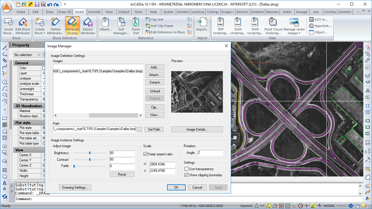
- Importing and editing raster images (eg geodesic underlay), including files such as : JPG, TIF, BMP, GIF, PNG.
- Import PDF files analogously to raster underlays or with conversion to vector elements.
- Export to PDF file.
- Possibility to enlarge the library of 2D / 3D objects with the following formats: XOBJECT, ACO, O2C, OBJ, XOBJ3D and DWG.
- IFC file conversion into ArCADia’s basic objects (walls, windows, doors, ceilings, roofs).
- Export of material lists of elements included in the project to RTF, CSV and to the Ceninwest program (which enables saving in ATH format of the Norma – Athenasoft program).
Drawing tools – an extended CAD drawing engine:
- Using DWT templates.
- The function of fixing and checking damaged files.
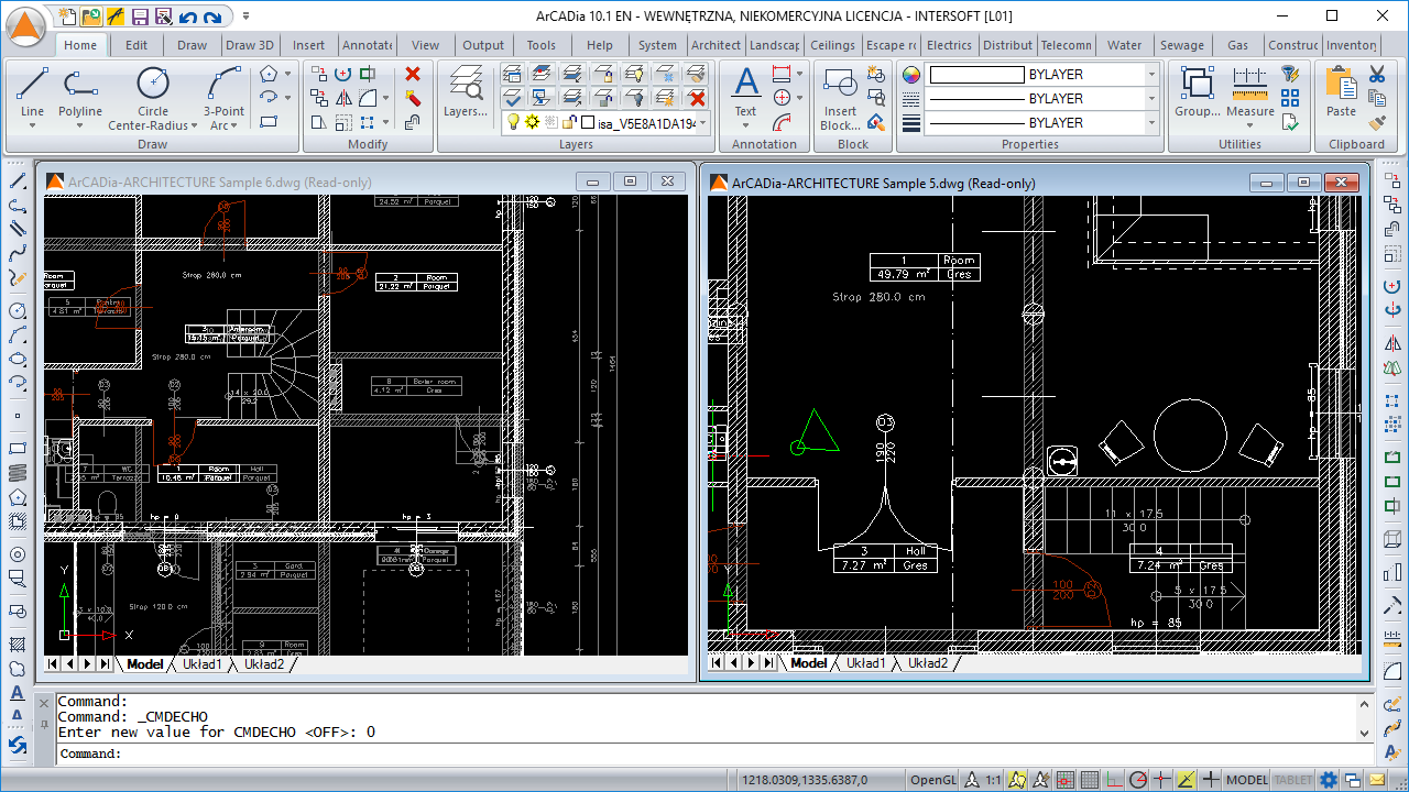
- The program window is divided into tabs in which the drawings are successively displayed.
- Command line and input
- Added new version of ODA Teigha 4.3.15
- Working on layers.
- Project management explorer.
- Working in cartesian and polar coordinates.
- Docked property panel.
- Displaying tool palettes.
- Dedicated Express tools toolbar.
- Possibility to create a non-rectangular viewport in the paper space.
- Implemented Lisp programming language interpreter.
- Possibility to load SDS and IRX overlays.
Drawing functions
- Basic tools for creating 2D and 3D drawings.
- Possibility to fully modify and edit the properties of all drawn elements.
- Dimensioning styles and text with the ability to import.
- Entering and defining symbol libraries, blocks, simple and complex texts (SHX and TrueType fonts). Additional multiline text editor.
- New functions of the word editor: columns, scaling, entering text along the arc and borders, text fitting, rotation, auto numbering, etc.
- Exploding attributes to text and exploding texts.
- Dimensioning assigned to the element: linear and angular, the ability to define your own styles.
- Automatic field and distance measurement, setting coordinates
- Combined command: Move / Copy / Rotate / Scale.
- New options for construction lines.
- Handles, attributes, hatches.
- A wide range of hatch patterns. New hatch definition and gradient fill window.
- A multiline drawing option.
- Enhanced block, reference and dimension support capabilities: block conversion to reference, copying nested objects (blocks, references and underlays), block/reference property list.
- Relative paths support for raster images and external links.
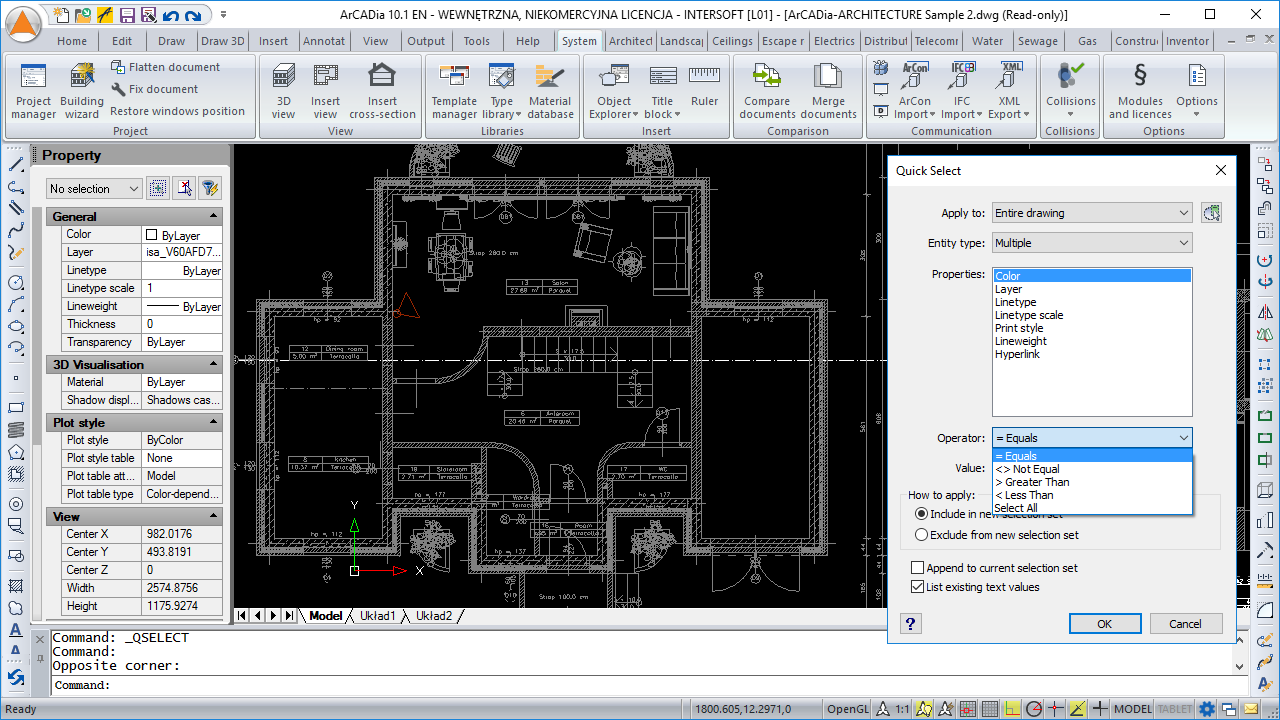
- Options: Select similar (with adding to the selection and the settings window), Multiadogy, Multiline editor, Dashed line.
- Displaying properties of the many selected elements in the form of a tree.
- Possibility to add point cloud in RCP / RCS format.
- New types of 3D objects (primitives) – Facet Modeler (ODA surface modeler), along with basic editing functions – intended for use in 3D, when the mass of the element is not significant.
- Possibility of photorealistic visualization and rendering.
- New function for camera settings in the view.
- Drawing in hidden line mode and shading in real time.
- Creating a project package and use of the eTransmit saving tool.
- Saving and displaying mechanical elements (Teigha Mechanical API).
- Displaying ADT and Civil 3D objects.
- Possibility to open ACIS solids (without option to create and fully editing).
Tools for precise drawing
- Auxiliary grid, orthogonal drawing functions, polar tracking.
- Extended recognition of snap points (ESNAP), e.g. for lines – center, end points and intersections of lines.
- Setting the snapping of characteristic points to underlays.
- Possibility to use a set of commands for construction lines.
- Expanded visualization – zoom, regeneration and panning of the drawing, dynamic rotation of 3D objects and a new function of camera settings in the view.
Import/export
- DWF, DGN and DAE formats support.
- Export of STL files.
Full personalization of the program
- Modification of the top menu, ribbons (panels and tabs), toolbars, command status bar and keyboard shortcuts.
- New ways of using the program interface, its settings and exporting the set profile.
- Configuration of the working screen: colour, cross-hair size, etc.
Why is it worth buying ArCADia BIM 11?
- It has a simple and user-friendly interface.
- Allows the designer to work according to BIM technology assumptions.
- It has been designed as a modular BIM system. The user has the option of gradually expanding the functionality, depending on the design needs.
- Provides the opportunity to cooperate with other designers – DWG file exchange, merge and compare design elements.
- ArCADiasoft is a member of the ITC. Some IntelliCAD 9 source codes have been used in the program.
System requirements:
- Intel Core 2 Duo or AMD Athlon II processor (Intel Core i5-6500 recommended)
- 3 GB RAM minimum (min. 12 GB and 64-bit system recommended)
- About 5 GB free hard disc space for installation (SSD recommended)
- for a basic 3D view a graphics card compatible with DirectX 9.0c 1GB RAM, for advanced 3D view compatible with DirectX 11 and min. 3GB RAM
- system: Windows 10 or Windows 8.1 or Windows 7 SP1 (Windows 10 64-bit recommended)


